Posted on

The Difference Between 2-Piece and 1-Piece Undercarriages

Landing gear generally comes in two basic configurations — a single continuous leg spanning the full width of the model, or two separate legs each bolted individually to their own side of the fuselage. Both are common, and the right choice often comes down to your specific airframe rather than a universal “better” option.

One-piece (spring/bow style) gear flexes as a single unit, which can give a smoother, more even landing feel since load on one side is partially shared across to the other through the continuous leg. It’s a simple, proven design used on a huge range of sport and scale models, and there’s generally one fewer set of mounting points to maintain.

Two-piece gear mounts each leg independently, which is often the only practical option on wider fuselages or models where a single-span leg simply wouldn’t fit the available mounting area. It also means a heavy landing that stresses one leg doesn’t necessarily transmit that load across to the other side — which some flyers see as an advantage, and others see as losing the shared-load benefit of a one-piece design.

If you’re replacing gear on an existing model, the honest answer is: match whatever configuration the model was designed around, since the fuselage mounting points and internal structure are usually built around one style specifically. Converting from one-piece to two-piece (or vice versa) on an existing airframe is possible but generally means reinforcing or modifying the mounting area — not a straightforward swap.

If you’re scratch-building or heavily modifying, it’s worth deciding early, since it affects fuselage design at the mounting area rather than being a late-stage decision.

Take a look at our Extra 330 Carbon fibre undercarriage 30e for a solid example of correctly sized gear.

Posted on

Protecting Your Landing Gear on Grass Strips

Grass strips are kinder to propellers than tarmac, but they’re not automatically kinder to landing gear — in some ways, quite the opposite.

Uneven ground concentrates shock loads unpredictably. A smooth tarmac landing spreads load evenly across a level surface. A grass strip with even minor undulation means one wheel can hit a slightly higher or lower point than the other on touchdown, putting an asymmetric load through the gear that a flat surface wouldn’t produce.

Longer or wetter grass adds drag exactly where you don’t want it — right at the wheel, right as the gear leg is already under load from touchdown. This is part of why wheel choice (see Day 7) matters as much as gear choice on grass strips specifically.

Rough or rutted ground rewards a slightly wider wheel and a slightly more generous gear stance if your model allows it — narrow, closely-spaced gear that’s fine on tarmac can feel noticeably twitchier on rough grass, with more load transmitted through each leg individually rather than shared smoothly.

A pre-flight walk of your usual strip is worth the two minutes it takes, especially early in the season after a wet winter — molehills, rabbit holes, and ruts that developed since your last visit are a common and entirely avoidable cause of hard, unexpected landing loads.

None of this means grass strips are bad for landing gear generally — most carbon fibre gear is more than capable of handling reasonable grass strip use for years. It just means the checks in Day 4 are worth doing slightly more often if grass is your regular home field, since the loading is genuinely less predictable than tarmac.

For a real-world example, have a look at our 1 Pair of Wheels with Plastic Hub for RC Airplane.

Posted on

Understanding Gear Leg Flex — And Why It Matters

Landing gear isn’t meant to be perfectly rigid, and that surprises some flyers who assume “stiffer is always better.” In reality, a certain amount of controlled flex is doing useful work every time you land.

When your model touches down, the gear leg absorbs a portion of the vertical energy by flexing, rather than transmitting all of that shock straight into the fuselage mounting points. This is the same principle full-scale aircraft undercarriage legs use, just without the oleo struts and hydraulics — a well-designed carbon fibre leg uses the natural spring properties of the laminate itself as a simple, maintenance-free shock absorber.

The trouble comes when flex crosses from “designed-in” to “developing damage.” A small amount of consistent, symmetrical flex under load, with the leg returning fully to its original shape, is normal and expected. Flex that’s asymmetric between the two gear legs, flex that doesn’t fully recover, or flex accompanied by any audible creak or crack, are all signs the leg is being stressed beyond its intended range.

This is also why gear sizing matters so much (see Day 1) — a leg designed for a lighter model, fitted to a heavier one, will flex more than intended on every single landing, accelerating fatigue long before any single landing looks dramatic enough to worry about.

If you want a rough real-world check, watch a landing on video in slow motion occasionally, or have a friend watch from the side. A small, even flex and rebound on both legs is exactly what you want to see — anything that looks lopsided is worth a closer inspection on the ground.

Our Carbon undercarriage for 50 size – 90 size profile models. is a good reference point if you’re shopping around.

Posted on

Wheel Pants and Carbon Gear — Getting the Fit Right

Wheel pants finish a model off beautifully, but they’re also one of the most common sources of frustration when fitting new landing gear, mostly because pant fitting is rarely as plug-and-play as the box suggests.

The core issue is tolerance stacking: your gear leg has a certain width and axle position, your wheel has a certain diameter and hub width, and your pant has a fixed internal cavity shape. Get any one of those slightly different from what the pant was designed around, and you’ll end up with rubbing, or a pant that sits at a slightly odd angle.

A few things that help:

Fit the gear and wheels first, pants last, and only trim the pant’s mounting slot once you can see exactly where the leg actually sits relative to the pant — resist the temptation to pre-drill mounting holes based on a diagram alone.

Leave a genuine air gap around the tyre, not just clearance when static. Tyres compress and the gear leg flexes rearward under load on landing, so a pant that just clears the wheel when the model is sitting still can make contact the moment you land.

Reinforce the pant mounting wire or bracket, since this is usually the first thing to fail — vibration loosens it long before the pant itself wears out. A drop of thread-lock and a periodic check goes a long way.

Accept that some trimming is normal. Even pants sold as a matched set for a specific gear rarely fit arrow-straight from the bag — a small amount of careful trimming with a sanding block is standard practice, not a sign you’ve bought the wrong part.

If you’re planning pants on a model that didn’t come with them designed in, it’s worth test-fitting before final paint — cutting a freshly painted pant to fit is a job nobody enjoys.

Our Wheel Spats is a good illustration of the kind of fit and finish to look for.

Posted on

Fitting New Landing Gear — A Step-by-Step Guide

Fitting new gear is one of the more satisfying jobs on any model, and it’s genuinely straightforward if you take it in order.

1. Remove the old gear completely, including any old thread-lock residue on the bolts, and inspect the fuselage mounting points for damage before fitting anything new — there’s no point bolting fresh gear to a cracked or soft mounting rail.

2. Dry-fit before you commit. Offer the new gear up to the mounting points without any fasteners tightened, and check the leg sits square to the fuselage centreline and that the wheel axles will clear any cowl, wheel pant, or fuselage side when the wheels are fitted.

3. Use the correct grade of fastener, torqued to a sensible value by feel rather than gorilla-tightened — carbon fibre mounting plates can crack under excessive clamping force just as easily as they can crack from flight loads. If in doubt, a drop of thread-lock on a moderately tight bolt beats an over-tightened one.

4. Check axle alignment with the gear bolted down — sight along both wheels from directly behind the model to make sure they’re parallel to each other and to the fuselage. Toe-in or toe-out, even slight, will cause the model to pull on take-off roll.

5. Fit wheels and pants last, and spin each wheel by hand to check for free rotation with no rubbing against pants or fuselage before your first flight.

6. Do a firm hand-push test on each gear leg, simulating a moderate landing load, before you ever trust it to a real one. If anything flexes further than you’d expect or you hear any cracking sound, stop and re-check the fit.

Take your time on step 3 in particular — most gear failures we hear about trace back to fasteners rather than the gear itself.

Take a look at our Carbon Fibre undercarriage for 50e and 50 size nitro Narrow Fit YAK50e 50e for a solid example of correctly sized gear.

Posted on

Five Signs Your Landing Gear Needs Replacing

Landing gear takes more repeated stress than almost any other part on the airframe, and yet it’s one of the most overlooked items on a pre-flight check. Here’s what to look for.

Hairline cracks or white stress marks. Carbon fibre doesn’t bend gracefully — instead, repeated stress shows up as fine white lines or surface cracking near the mounting points or the tightest curve of the leg. Any visible cracking means retirement, not repair.

A leg that no longer sits level. If one side of your gear sits noticeably lower or at a different angle than the other after a hard landing, even without visible damage, there may be internal fibre damage you can’t see. A gentle flex test (by hand, gear off the model) comparing both legs side by side is a good habit.

Loose or elongated mounting holes. Repeated vibration and shock loading can wear out the mounting holes over time, particularly on models that see a lot of grass strip use. Elongated or oval holes mean the gear is no longer being held rigidly, which accelerates wear elsewhere.

Wheel wobble that wasn’t there before. Sometimes it’s the axle or wheel collet rather than the gear itself, but a wobble that’s developed gradually is worth investigating properly rather than tightening and ignoring.

You genuinely can’t remember when you last replaced it. Carbon fibre landing gear doesn’t have a fixed service life in hours, but if a leg has seen several seasons of regular grass strip landings, it’s earned a proper inspection at minimum.

None of this needs to be expensive or complicated — a five-minute check before the season starts, and after any landing that felt harder than usual, catches almost everything above before it becomes a real problem.

For a real-world example, have a look at our Carbon Fiber Landing Gear For 26cc-35cc / 50cc / 80cc / 100cc / 150cc / 200cc Airplane Flight.

Posted on

Fixed Gear vs Retracts — Pros and Cons for Scale Aerobatic Models

Retracts look fantastic in the air and add a real touch of scale realism, particularly on Yaks, Extras, and other full-scale aerobatic types that were built with retractable gear. But they’re not the right choice for every flyer, so it’s worth being honest about the trade-offs.

Fixed carbon fibre gear is simpler, lighter, cheaper, and has far fewer failure points — no servos, no sequencers, no mechanical linkages to maintain. For sport flying, training, and even a lot of competition aerobatics, fixed gear is genuinely the more practical choice, and plenty of full-scale aerobatic aircraft (including many Extras) fly perfectly well with fixed gear in real life too.

Retracts add weight, complexity, and cost, and they introduce a failure mode that fixed gear simply doesn’t have: a retract that won’t come down. For sport and club flying, that’s usually just an embarrassing (and expensive) belly landing. For a model you’ve spent serious money and time on, it’s a real consideration.

If scale accuracy is a priority for you — flying at a scale competition, or your particular subject was retract-equipped in real life — retracts are worth the extra complexity. If you’re mainly flying for fun, 3D, or general sport aerobatics, don’t feel you’re missing out by sticking with fixed carbon gear; most judges and spectators won’t mark you down for it, and your maintenance list will be considerably shorter.

Whichever route you take, gear leg dimensions and mounting patterns are broadly similar between fixed and retract setups on a given airframe size, so our sizing charts apply either way.

Our EXTRA 300 150CC Carbon Fibre undercarriage is a good reference point if you’re shopping around.

Posted on

Carbon Fibre vs Aluminium Landing Gear — Which Is Right for You?

Both materials have a long history in RC undercarriages, and both still have their place — the right choice depends on what you fly and how you fly it.

Aluminium gear has been the traditional default for decades. It’s forgiving, relatively cheap to produce, and it fails predictably — a hard landing tends to bend it rather than snap it, which some flyers actually prefer because a bent leg is a visible warning sign, and often can be bent back into rough shape in a pinch.

Carbon fibre gear is lighter for a given stiffness, which matters most on 3D and aerobatic scale models where every gram affects the power-to-weight ratio and where a stiffer leg means less energy absorbed as unwanted flex during hard 3D landings and torque rolls. The trade-off is that carbon doesn’t bend and re-use the way aluminium does — under enough stress it will crack or delaminate rather than deform, so inspection after a heavy landing is more important.

Neither is objectively “better” — a sport pilot flying smooth grass strips off a 50cc Yak may never stress aluminium gear enough to notice the difference, while a competition 3D flyer landing hard and often will feel the benefit of carbon’s stiffness immediately.

If you’re upgrading rather than replacing like-for-like, it’s worth checking your model’s designed all-up weight against the gear’s rated range — going carbon on an overweight model won’t fix a fundamental mismatch between weight and leg stiffness.

You can browse our Carbon Undercarriage for 30 size nitro / electric sized RC models to see this in practice.

Posted on

What Size Carbon Fibre Landing Gear Does My RC Plane Need?

One of the most common questions we get is simply: “which size do I need?” It’s a fair question, because unlike a lot of RC parts, landing gear isn’t sold by a universal sizing standard — it’s matched to the airframe and, often, to the engine size the model was designed around.

The starting point is always your model’s manual or manufacturer spec sheet. Most kit and ARF manufacturers will state a recommended engine displacement (in cc for petrol/glow, or a motor/prop combo for electric), and gear is generally sized to match that bracket — for example 26cc-35cc, 50cc, 80cc, and so on up to 200cc+ for the larger scale aerobatic types.

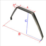
If you no longer have the original documentation, the next best method is measuring your existing gear (or the mounting points on the fuselage if you’re starting from bare wood or foam) and comparing against the dimension charts on each product page — fuselage width, undercarriage widh and track are the three measurements that matter most. you will see on most of our undercarriages a diagram with A, B, C and D measurements. compare these with what you have, or had, and you can start working on a suitable replacement.

Undercarriages

A word of caution: “close enough” isn’t good enough with landing gear. Too light a gauge for your model’s weight and you risk flex or fatigue cracking after repeated landings; too heavy and you’re carrying unnecessary weight for no benefit. If you’re between two sizes, it’s almost always worth sizing up rather than down, particularly if you fly from grass.

One thing to consider is putting in an undercarriage in two parts. by splitting it in half at the ‘A’ measurement, allows you to both widen or narrow an undercarriage that may be right in all other aspects but not fit across the fuselage. Good bolts and fixings help with split undercarriages and many large models come originally with split undercarriages.

If you’re ever unsure, get in touch with your model, engine size, and roughly all-up weight, and we’re happy to help you land on the right choice before you order.

Our Carbon Fibre Undercarriage for 100cc models – suits Yak and others. UK stock is a good illustration of the kind of fit and finish to look for.

Posted on

RCEXL Ignition Systems

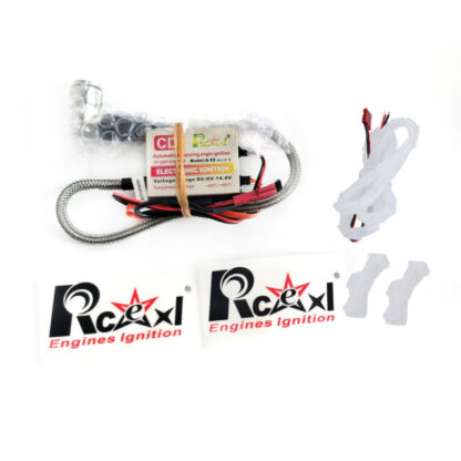
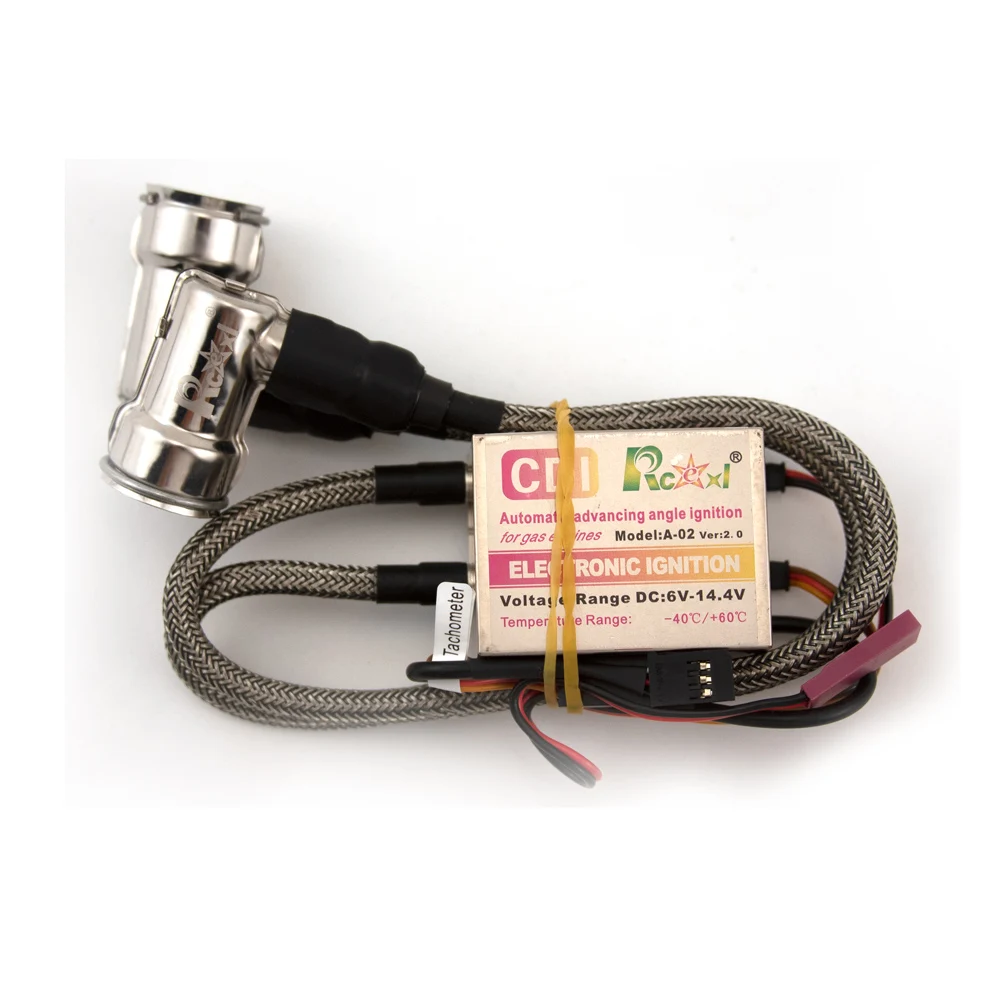
Rcexl Single/ Twin Electronic Ignition System CDI W/ Sensor NGK BMR6A-14MM 90 Degree Spark Plug Special For Gas Petrol Engine

RCEXL Ignition Systems: A Complete Guide to Choosing the Right CDI for Your Petrol Engine
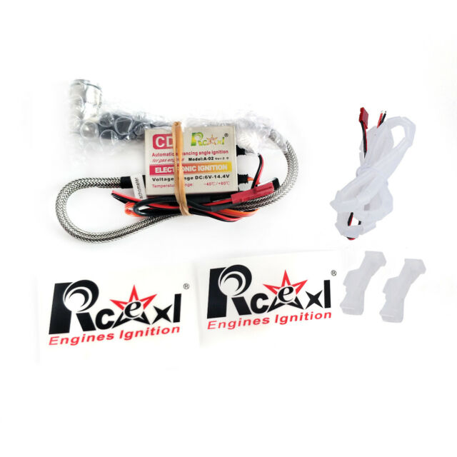
RCEXL Ignition Systems

If you’re running a petrol/gas engine in your RC model, the ignition system is one of those components you never think about — until it lets you down. A weak spark, a fried module, or the wrong plug cap fitment can ground a model on flying day. That’s why so many UK modellers standardise on RCEXL ignition systems for their single and twin cylinder engines.

Prices start from £53.45, with the exact price depending on which single or twin configuration you need.

Here’s what you need to know before you buy, and how to pick the right one from our range.

What Does an RCEXL Ignition System Do?

An RCEXL ignition (CDI, or Capacitor Discharge Ignition) generates the spark that fires the fuel-air mixture in a petrol/gas engine, in the same way a car’s ignition coil does — just scaled down and built to survive the vibration, heat and G-forces of an RC airframe.

RCEXL units are a popular choice because they:

  • Run reliably across a wide 6V–14.4V input range, so they’re compatible with 5-cell NiMH packs, 2S LiPo, and 3S LiPo batteries without extra regulation
  • Are available for both single and twin cylinder engines
  • Come in multiple cap angles (Straight, 90°, and 120°) to suit different cowl and engine layouts
  • Fit a wide range of popular engine plug types

Choosing the Right Model: Plug Type Matters Most

The single biggest decision when ordering an RCEXL ignition is matching the plug/cap type to your engine. Get this wrong and it simply won’t fit. Our range covers four common cap fitments:

Plug Type Fits
ME-8 1/4-32 Common on many popular single and twin petrol engines
CM-6 – 10MM 10mm cap fitment, found across several popular engine ranges
BMR6F – 14MM 14mm cap fitment
BMR6A – 14MM 14mm cap fitment, alternate spec

If you’re not sure which cap your engine uses, check your engine’s manual or the existing ignition module fitted — it’s far easier to match an existing part than to guess.

Cap Degree: Straight, 90°, or 120°?

Once you know your plug type, the next choice is the angle of the cap itself. This is purely about physical clearance inside your cowl:

  • Straight — where you have room for the lead to run directly off the plug
  • 90° — the most common choice, ideal for tight cowls where the lead needs to turn sharply away from the cylinder head
  • 120° — a shallower angle, useful for certain engine and cowl geometries where a full 90° bend won’t clear

If you’re replacing an existing ignition, matching the old cap angle is usually the safest bet.

Single vs Twin: Match It to Your Engine

We stock both:

  • Single ignition systems (model numbers 1121–1128) — for single cylinder petrol/gas engines
  • Twin ignition systems, Version 2 (model numbers 1221–1228) — for twin cylinder engines, firing both cylinders from one unit

Each is available across the same range of plug types and cap angles listed above, so once you know your engine’s fitment, choosing between single and twin is simply a matter of matching your cylinder count.

Quick Fitment Reference

Model Configuration Plug Type Cap Angle
1121 Single ME-8 1/4-32 90°
1122 Single ME-8 1/4-32 120°
1123 Single ME-8 1/4-32 Straight
1124 Single CM-6–10MM 90°
1125 Single CM-6–10MM 120°
1126 Single CM-6–10MM Straight
1127 Single BMR6F-14MM 90°
1128 Single BMR6A-14MM 90°
1221 Twin ME-8 1/4-32 90°
1222 Twin ME-8 1/4-32 120°
1223 Twin ME-8 1/4-32 Straight
1224 Twin CM-6–10MM 90°
1225 Twin CM-6–10MM 120°
1226 Twin CM-6–10MM Straight
1227 Twin BMR6F-14MM 90°
1228 Twin BMR6A-14MM 90°

Why Buy From Carbon RC Parts?

RCEXL Ignition Systems

We stock the full RCEXL ignition line-up as standard, single and twin, across every cap type and angle, so you can order the exact spec your engine needs rather than settling for whatever happens to be in stock elsewhere. Selected models are held in UK stock for faster dispatch.

Prices start from £53.45 (Aug 2026), varying by single/twin configuration, plug type, and cap angle — see the reference table above for the full line-up.

While you’re fitting a new ignition, it’s also worth checking your kill switch — our RCEXL RXE2207 Big Power TOC Switch with Futaba plug is a popular pairing and a sensible thing to replace at the same time if your current one is showing its age.

Browse the full RCEXL Ignition Systems range →

Not sure which model fits your engine? Get in touch and we’ll help you find the right part before you order.